On This Page
Introduction
A conveyor pulley is manufactured around a defined mechanical interface, not around a product name alone. Shell diameter and face width are visible starting points, but the shaft geometry, bearing centres, hub or end-disc construction, connection method, lagging and allowable loads determine whether the finished assembly will fit and operate in the intended conveyor. For an overseas buyer, the value of understanding the conveyor pulley manufacturing process is practical: it shows which information must be settled before steel is cut and which checks should be included in the purchase scope.
Hebei Junxin Conveyor Machinery reviews pulley work from the approved drawing and application data. Production planning links the shell, end structures, shaft and bearing interfaces to the same revision. Buyers evaluating our conveyor pulleys should provide the conveyor position, loading information and full installation dimensions so the workshop does not have to infer critical details from a nominal diameter.

Junxin Manufacturing Perspective
Pulley quality depends on the sequence connecting shell preparation, hub and shaft alignment, welding, machining and final inspection. Junxin confirms load data and interfaces before release because later machining cannot correct every design or fabrication error introduced earlier in the route.
Conveyor Pulley Structure
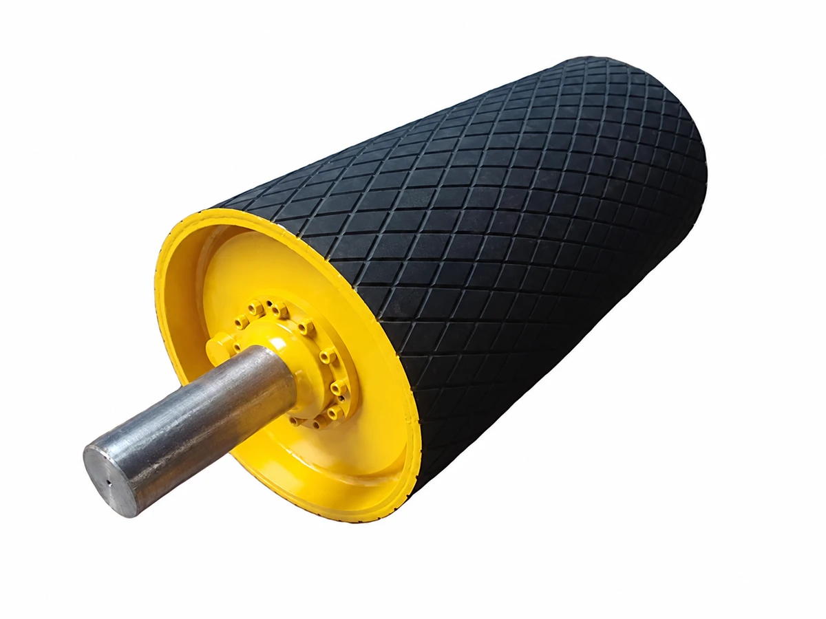
The shell provides the belt-contacting surface and transfers load into the end structures. Its outside diameter, wall or finished construction, face width and surface treatment depend on the pulley duty. Drive pulleys may require a specified lagging system and a connection capable of transmitting torque. Bend, tail, take-up and snub positions have different load directions and interface requirements even when two pulleys appear similar.
End discs or hub structures connect the shell to the shaft system. Their geometry affects load transfer, weld layout and machining allowance. The shaft carries bending and torsional loads and includes the bearing seats, shoulders, keyways, threads, coupling end or other installation features shown on the drawing. Bearing centres and shaft extensions must match the supporting structure and drive arrangement. These details also connect the pulley to the wider belt conveyor system, so a change to one interface should be reviewed against the assembly rather than made in isolation.
Lagging or another surface system may be added for traction, wear or environmental requirements. Rubber type, thickness, pattern and bonding specification should be stated where relevant. Ceramic elements or other specialized surfaces require their own approved scope. The drawing should distinguish the steel shell dimensions from the final outside diameter after lagging.
Manufacturing Challenges
The main production challenge is maintaining alignment while several large components are formed, machined, fitted and joined. Shell roundness, end-structure location and shaft alignment influence finished runout. Welding introduces heat, so sequence and restraint must be considered to manage distortion. Machining allowances must be sufficient for the required final surfaces without hiding a dimensional problem created earlier in the process.
Load and torque requirements also affect construction. A pulley selected only from belt width may not have an appropriate shaft, shell or connection for the conveyor duty. The manufacturer needs belt tensions or design loads, drive information where applicable, wrap angle, speed, bearing arrangement and operating environment. If the buyer supplies an existing drawing, the revision and any site modifications should be identified. A custom conveyor pulley manufacturer should not change a critical section or interface without technical confirmation.
Another challenge is inspection planning. Large workpieces cannot be evaluated by appearance alone. Buyers should define which diameters, widths, bearing seats, keyways, centre distances, runout values, weld requirements and surface details will be accepted. If nondestructive examination, balancing, material certificates or coating reports are required, the method and acceptance basis should be agreed in advance.
Pulley Shell Fabrication
Shell preparation begins after the material and finished dimensions are confirmed. Depending on the approved design, the shell may be prepared from suitable tube or fabricated plate. The workpiece is cut with allowance for the planned forming, welding and machining route. Edges and joint areas are prepared for the specified connection, and the initial condition is checked before end structures are fitted.
For a fabricated shell, controlling the cylindrical form is important because out-of-roundness carried into assembly increases the machining required later and may affect the final wall condition. End faces and reference surfaces need to support accurate location of discs or hubs. The workshop should identify the reference used for subsequent machining so diameter, face width and shaft centreline are controlled as one assembly.
After fitting and welding operations, the shell can be machined to the required surface and dimensional condition. The exact sequence depends on the drawing, workpiece size and connection method. Enough allowance must remain for final turning while the finished dimensions stay within the approved design. Any grooves, crown profile or lagging preparation should follow the ordered surface specification.
Shaft Machining
The shaft drawing should define the raw material requirement and every functional section. Machining commonly includes the main diameter, bearing seats, shoulders, retaining features, keyways, threads and drive or coupling interfaces. Bearing-seat diameter, surface condition and shoulder location are especially important because they affect bearing fit and the installed position of the pulley.

Machining should use consistent datums so the bearing seats and drive features remain aligned. The workshop also needs a practical way to handle and support a long or heavy shaft without introducing avoidable error. Dimensions are checked during the operation rather than left entirely to final inspection. Where the design uses removable locking elements or a keyed connection, the mating component specification should be available for review.

A replacement pulley enquiry should include more than the exposed shaft extension. Bearing centres, seat diameters, shoulder positions and both end details must be recorded. If only one side is measured, differences between the drive and non-drive ends can be missed. Photographs are useful for orientation, but a dimensional drawing or verified measurement sheet remains necessary.
Welding and Assembly
Before welding, the shell, end structures and hub or shaft arrangement are fitted to the approved geometry. Alignment and location checks at this stage reduce the risk of correcting the assembly after heat has been introduced. Joint preparation, welding process, sequence and any preheat or examination requirement should follow the approved manufacturing specification for the ordered construction.
Heat input and weld sequence can influence distortion. The workshop therefore needs to monitor the assembly between stages and retain the machining allowance needed for final correction. Welds should be accessible for the specified visual or nondestructive examination. If the design includes stress-relief or another post-weld treatment, it must be identified before the machining route is finalized.
Assembly continues with the shaft connection, keys or locking elements, bearings or housings where they are part of the supply, and any guards or accessories listed in the order. The conveyor pulley supplier should make clear which items are factory assembled, which are shipped separately and which are supplied by the buyer. This avoids confusion during installation and packing.
Quality Inspection
Final inspection starts with the approved drawing and purchase requirements. Dimensional checks may include shell diameter, face width, overall shaft length, bearing-seat diameters, bearing centres, shaft extensions, keyways, threads and other mounting interfaces. Runout should be measured at the agreed surface and position. The report should identify the item, drawing revision and measured characteristic when formal records are requested.
Weld inspection depends on the specified construction and service requirement. Visual inspection is a basic step; additional examination should be stated by method, location, coverage and acceptance standard. Material certificates, hardness checks or other tests are included only when agreed. The same applies to static or dynamic balancing: the required method, grade or acceptance value and the pulley condition during balancing should be defined in the enquiry.
Surface inspection covers the ordered finish. For painted steel, buyers may specify surface preparation, coating system, colour and dry-film thickness. For lagged pulleys, the review may include material, thickness, pattern, coverage, edge condition and visible bonding quality. Identification, lifting or handling points and package protection are checked before dispatch according to the confirmed order.
Customization Options
Customization can cover pulley position, diameter, face width, shell and end-disc construction, shaft geometry, bearing interfaces, drive connection, lagging, coating and inspection documents. The practical limit is not whether a feature can be drawn; it is whether the design inputs are sufficient to verify it. Junxin reviews customer drawings and application information before confirming a production route.
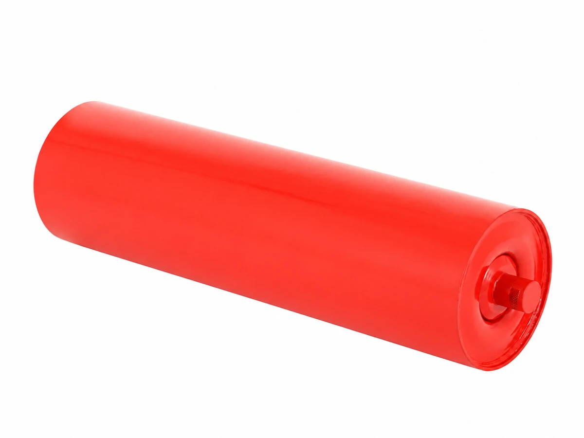
Drive pulleys require clear torque and connection information. Bend, tail, snub and take-up pulleys require their load direction, bearing arrangement and installation envelope. Replacement work should identify the existing bearings, housings, coupling and support structure. If the order also includes conveyor idlers, the pulley and roller interfaces can be reviewed within the same equipment documentation while remaining separate manufactured items.
Buyers should distinguish mandatory requirements from preferences. Mandatory dimensions and acceptance criteria belong on the approved drawing or purchase specification. Preferences such as marking format, paint colour, spare fasteners or photo records should also be written into the order so they can be planned rather than requested at the packing stage.
How To Prepare A Pulley RFQ
A useful pulley RFQ allows the manufacturer to understand function, loads, interfaces and supply boundaries. Include the following information:
- Pulley position: drive, tail, bend, snub, take-up or another defined location.
- Belt width, belt speed, wrap angle and operating direction.
- Design tensions, torque, allowable loads or the conveyor calculation used for selection.
- Shell diameter, face width, shell construction and required finished surface.
- Complete shaft drawing with bearing seats, centres, shoulders, keyways, threads and coupling details.
- Bearing and housing information, including whether they are included in the supply.
- Lagging material, thickness, pattern and final diameter where applicable.
- Operating environment, temperature, dust, moisture, corrosion and duty cycle.
- Welding, nondestructive examination, balancing, coating and documentation requirements.
- Quantity, spares, marking, packing, delivery basis and required schedule.
Attach the current drawing revision and identify any dimensions that still require confirmation. If the RFQ is based on an existing pulley, provide measurements, photographs and equipment references, but avoid treating a worn surface as the intended original dimension. A technically complete RFQ helps the buyer compare quotations on the same basis and gives the workshop a clear route from material preparation to final inspection.
Frequently Asked Questions
What information is required to manufacture a custom conveyor pulley?
Provide the pulley position, belt data, design loads or torque, shell diameter and face width, complete shaft and bearing interfaces, surface or lagging requirement, environment, quantity and inspection scope. An approved drawing is required before production.
Which dimensions are most important for a replacement conveyor pulley?
Confirm the shell diameter, face width, bearing centres, bearing-seat diameters, shaft extensions, shoulders, keyways, threads and drive connection on both ends. Also identify the existing bearing housings and supporting structure.
Can pulley lagging be customized?
Lagging can be reviewed by material, thickness, pattern, coverage and application requirement. The buyer should state whether the quoted shell diameter is before or after lagging and provide any bonding or inspection specification required by the project.
Should balancing or nondestructive examination be included in the RFQ?
Include them when required by the pulley duty, project specification or buyer's inspection plan. State the method, coverage, acceptance standard and pulley condition so the manufacturer can include the correct process and documentation in the quotation.